Using a Logic Probe
Huh? I Have To Know How The Circuit Works?? And What's This Datasheet Thing?
Yes,
you'll need to learn something about how the part of the circuit you're
examining works in order to help isolate and diagnose the issues that
are occuring. It may not be easy at first if you've never looked at a
schematic or datasheets, but it will get much easier over time. If you
don't know what a schematic or datasheet is, then you may want to start
learning about those things prior to using a logic probe.. otherwise the
HIGH and LOW the logic probe outputs will be meaningless.
Reading datasheets doesn't have to be too difficult. Datasheets contain all of the information necessary to use a component and stay within its operating voltages, temperature, etc. For ICs they describe the functionality of the pins (inpus and outputs) and often contain logic diagrams showing the logic of the components within the IC. They also often describe what signal (HIGH, LOW) on the input is needed to get a desired signal on the output.
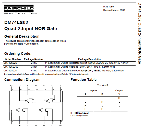
Let's take a quick look at a datasheet for a 74LS02 Quad 2-Input NOR Gate (logic IC)..

Lots of information and this is only on the first page of the datasheet. But you don't need to know what all of the information is right off the bat or at all. In the datasheet above, the "Connection Diagram" shows the various pins of the 74LS02. Pin 7 is GND, pin 14 is VCC +5v. The rest of the pins are inputs and outputs.. and the functionality of those inputs and outputs is shown in the Function Table.
The 74LS02 is a "Quad" 2-Input NOR Gate. This means there's (4) 2-Input NOR Gates. You could use 1 set of gates or you could use all 4 sets. Each set uses 3 pins -- 2 input pins (A and B) and 1 output pin (Y). So looking at the Function Table you can see the truth table containing all of the possible combinations of input and output signals for these pins. On the first line it shows that if input A is LOW and input B is LOW then the output will be HIGH. The second line shows that if input A is LOW and input B is HIGH the output will be LOW. And so forth.
So how does this help you? Well, if you know that the output pin of this IC should be LOW until you press a button, at which time it should go HIGH.. then you could use the logic probe on the output pin. Initially without pressing the button it should say LOW. If the logic probe showed the output signal (Y) was stuck HIGH then you would then want to check the signals on both of the inputs (A and B) to see if one of the signals is HIGH. If the inputs signals were LOW and output signal was HIGH then it's very likely the 74LS02 is bad. If however one of the input signals is HIGH then the problem is likely further up in the circuit (whatever is sending the HIGH signal to the 74LS02). That's how a logic probe can help diagnose a circuit. If you know what a signal should be at a certain point in a circuit and the logic probe shows otherwise, then you can use the logic probe to help isolate what is causing the bad signal.
Conclusion
A logic probe can't tell you whether a HIGH
or LOW signal is expected, that is for you to determine based on what
you know about how the circuit should work. Logic probes are very
useful to diagnose certain problems, but they are just a tool and YOU
are the interpreter. If you don't know anything about how the circuit
you're trying to diagnose works or how any of the components work, the
output of the logic probe won't tell you anything except that there's
voltage or no voltage. If however you learn a little about how the
circuit should function under normal conditions and how some of the
components work, a logic probe can be used to isolate the faulty
component.
I hope this is all making some more sense now. The best way to learn how to use a logic probe is to start using a logic probe today! If you can hook up a simple 5v circuit with something like the 74LS02, ground both of its inputs and then read the output pin with the logic probe.. you will start understanding how you can harness the power of this new tool for your evil genius projects or repairs. Good luck!
page1 page2 page3 page4Comments:
| Re: Great article. |
| Posted 09/30/12 10:55AM by AceBHound |
| Thanks for pointing out the spelling mistake! Always happy to fix any of those cause they drive me nuts too =) |
| Great article. |
| Posted 09/27/12 5:01PM by Anonymous Techdoser |
| Great article. Just one small nit-picking point. On page two, you use the word "here" when you mean "hear". Sorry about that. I saw this mistake made twice today. |
