Wiring Multiple LEDs
LEDs in Series
Wiring LEDs in series is pretty easy -- and a great way to learn how wiring in series affects the voltage and current on the circuit. In college, they taught us with actual light bulbs with sockets that we'd clip together in series with various leads -- ah, the good old days!
When wiring up any electrical circuit, the equation V=IR (otherwise known as Ohms Law) is imporant in figuring out the voltage and resistance at various points and the limits of the circuit. An interesting thing with series circuits is while the voltage drop will change based on the number of components you're hooking up, the current remains the same across the entire circuit.
Voltage = Current * Resistance
So V=IR can be rewritten V/I = R:
Voltage / Current = Resistance
So lets figure out how many resistors would be needed to connect two LEDs "in series":
(6v supply - 3v led - 3v led) / 0.02 Amps = Resistance
0v / 0.02 Amps = Resistance
Since 0 divided by anything is still 0, no resistors are needed.
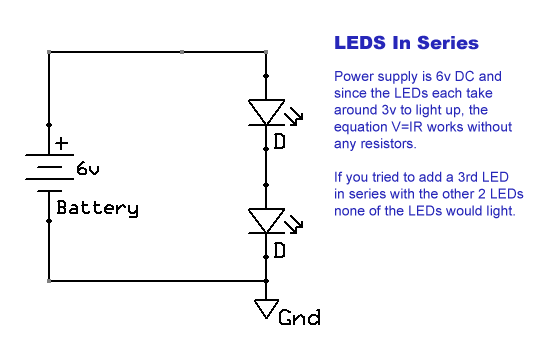
Thus, the circuit would look something like this:
Why no resistors? When wiring in series, the current remains the same across the circuit, but the voltage still changes based on the number of components being hooked up. So since both LEDs need around 3v to light up, they're essentially using all of the 6v of the power supply in that circuit up and balancing some complex equations. If you had a 9v power supply, you could wire up 3 LEDs in series.. however with just a 6v power supply if you tried adding a 3rd LED the voltage drop of 9v would exceed the power supplies voltage enough that the LEDs wouldn't be getting the ~3v voltage they need to operate. This is probably why we used light bulbs in college, cause you would see the bulbs starting to dim as you hooked more and more bulbs in series, whereas an LED is more finicky about voltage requirements.
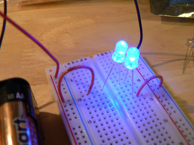
Below is a picture of two LEDs wired in series on my breadboard with a 6v battery supply as in the schematic. Notice that that (from left to right) the positive rail of the power supply connects to a jumper. The jumper connects to the anode of the first LED. The cathode of the first LED is then in the same row as the anode of the second LED. And the cathode of the second LED is in a totally different row that is then connected to the ground rail to complete the circuit.
Next lets take a look at wiring LEDs in parallel..
Comments:
| HOW DO YOU WIRE A ROW OF UV LIGHTS? |
| Posted 09/11/13 8:38AM by jbing |
|
I am making UV Lights for Ghost Hunting. I cant seem to figure out how to wire them correctly. I cant get all the lights the light evenly, they all have a different brightness. here are the specs on the leds. DC Forward current=20mA Voltage=3.2-3.4 I am powering them with a 9volt batt. I have UV Leds in a box. Can any 1 help me wire them correctly? Thank You |
| wiring multiple led |
| Posted 03/13/13 8:56PM by treehuggerz |
| Hi I'm really new to this I'm trying to make a uv led writing board i want to use 9 uv leds 5mm each are 3.3 fw supply and 20 ma fw current im confused should i make 3 in each series and then run the sets of series in parallel or can i just run 9 leds in parallel i dont care how often. I have to change the battery.... also if you need 150 ohm resistance and you are running in parallel would you put 150 in front of each led or should you divide the resistance by how many leds you are using . Thanks so much for any help i have pictures of what I'm trying to do if that helps you help me :) |
| wiring multiple led diodes |
| Posted 02/01/13 8:40AM by mangrav |
| Hi, I have a rechargeable 2ft emergency twin ordinary tube light with 6v battery integrated. I want to remove the tube light and adjust it with 30 led diodes of 5mm, 20mA using the same circuit. Can you please help me in choosing the right resistors and making the wiring? |
| connecting blue uv led to insect zapper in lieu of uv tube lamp |
| Posted 04/12/12 10:08AM by kotakstreet |
| would be grateful if you can give me a circuit to connect 6 uv led working on 220v & 6v dc |
| Resistor before or after the LED |
| Posted 02/02/12 10:59AM by Anonymous Techdoser |
| It doesn't matter whether the resistor goes before or after the LED. The factor that burns out components is CURRENT, not VOLTAGE. The current through each loop in the circuit is the same whether the resistor is placed before or after the LED. |
| 3 L.E.D |
| Posted 10/03/11 3:53AM by ajaykumargaur |
|
Hi, I have seen some circuit in the market, which have 3 color chaning LED in series and the circuit is operated from 220 Volts. I have the same but the resistance inside it gets burn on inverter, can any one help on this? |
| Electron flow vs. Current flow |
| Posted 02/04/11 6:02PM by Anonymous Techdoser |
| To answer why the resistor is connected after the led is because of a misunderstanding of the flow of electricity before the electron was actually discovered, the electrons flow from negative to positive. So if you look at the schematic and follow the path from the negative terminal of the power supply - through the resistor - through the LED - back to the positive terminal of the power supply. |
| Resistor after LED |
| Posted 10/23/10 4:03AM by Anonymous Techdoser |
| Basically speaking current flows from negative to positive so the resistor is in front of the LED. |
| Will the required current be across each led? |
| Posted 06/29/10 10:32AM by Shoaib |
| I am in doubt about the current across each parallel diode. If the required current across each diode is 25mA, How can I maintain this amount of current across each diode? |
| why is the resistor connected after the led |
| Posted 06/05/10 3:02AM by try.myx |
|
as in your circuit diagram in the wiring multple led , why is the resistor connected after the led . isnt it supposed to be in front. now im in doubt. From the way i think and understand the resistor is used to minimise the voltage. so that the led will not recieve excess of voltage from burning it. please clear me the doubt . thnx in advance |
